We use Geometric Dimensioning and Tolerancing in parts and assemblies drawings to define the theoretical (nominal) value of each geometrical feature and the allowable tolerances (variation) between those features. That is to say, there are different standards that we use for GD&T. The standard that we work with, at Precision Measurement and Design, is ASME Y14.5 which provides a complete set of standards for GD&T in one document. The ISO standards, in comparison, typically only address a single topic at a time.
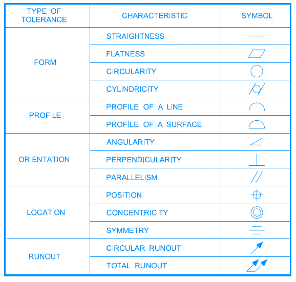
The front chart represents the geometric tolerancing reference. The straightness, flatness, circularity, and cylindricity which controls the form, don’t require any datum reference. However, the rest of the characteristics such as profile, true position, run out, … need datum reference.
We also use “feature control frame” to specify a feature’s description, tolerance, modifier and datum references. The most common FCF are free state (F), maximum material condition (M), and least material condition (L).